
TM 5-4520-208-15
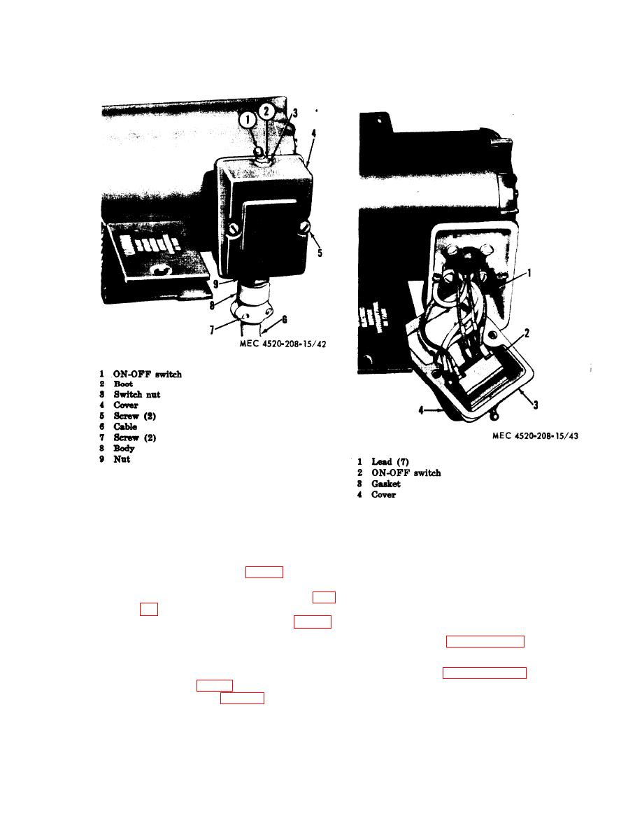
Figure 42. ON-OFF switch and cable removal points.
ware, improper operation, or other
damage. Replace defective ON-OFF
Figure 43. ON-OFF switch, removal points.
switch. Replace damaged cover or
gasket.
106. Cable and Connector
d. Installation.
a. General. The 4-conductor cable is con-
(1) Position gasket (3, fig. 43) in cover
nected to the terminal block at the rear of the
(4). Position ON-OFF switch in cover
ON-OFF switch. A cable connector attaches the
and secure with switch nut (3, fig.
cable to the junction box cover.
(2) Connect the tagged leads (1, fig. 43)
b. Removal.
In terminal block at rear of ON-OFF
(1) Refer to paragraph 12 and remove
switch (2).
electric motor power unit.
(3) Position cover, with attached switch,
(2) Refer to paragraph 105 and remove
on junction box and secure with two
junction box cover and disconnect ca-
screws (6, fig. 42).
(4) Install cabinet (para 12).
ble leads from ON-OFF switch.
75

