TM 9-4520-258-14
4-24. CONTROL BOX ASSEMBLY - continued.
a.
Disassembly - continued (Refer to Figure 4-26)
(3)
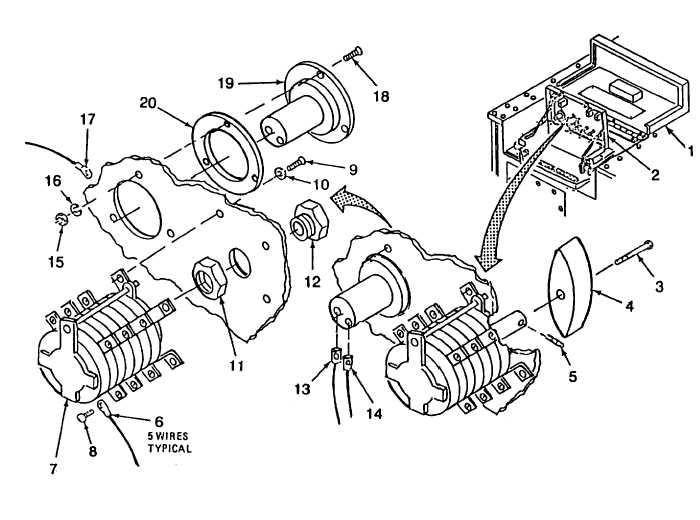
Tag and disconnect sixteen wires (6) from MODE switch (7) by removing thirteen screws (8).
(4)
Remove four screws (9), four preformed packings (10) and MODE switch (7).
(5)
Remove nut (11) and sleeve (12).
(6)
Tag and disconnect wires (13) and (14).
(7)
Remove three self-locking nuts (15), three flat washers (16), ground wire (17), three screws (18), hour
meter (19) and gasket (20). Discard gasket.
4-95