T M 9 - 4 9 3 1 - 3 8 1 - 1 4 & P - 2
FRAME 12
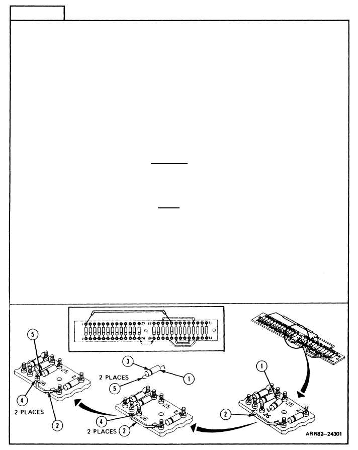
Remove Semiconductor Device or Fixed Film Resistor:
NOTE
l
Read Paragraph 2-4 on tagging and crimping wires
before doing any work.
l
Use this task to replace any of 16 semiconductors or 10
resistors. Semiconductor CHR13 (1) is shown.
l
Take off jumper wires as required.
1.
Unsolder and take off semiconductor (1) and jumper wire (2), if any. Get rid of
semiconductor (1).
Install Semiconductor or Fixed Film Resistor:
CAUTION
Installing semiconductor (1) backwards can cause damage to
panel Iamps. Make sure the band (3) on the semiconductor
(1) is facing the correct terminal (4)
NOTE
Put on jumper wires as required.
2.
Wrap leads (5) of new semiconductor (1) and
as shown below.
jumper wire (2), if any, around two
terminals (4).
3.
Solder leads (5) and jumper wire (2), if any, to terminals (4).
Follow-on Maintenance:
NOTE: To install board assembly A1TB1, refer to task 23.
TASK 6 ENDS HERE
Volume IV
Para. 2-6, Task 6
2-49