TM 10-4520-262-12&P 0012 00
0012 00-2
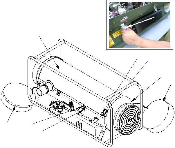
1. Disconnect electrical connector (1) from flame sensor (2).
2. Using wrench (3) supplied with the heater, unscrew flame sensor (2) in counterclockwise direction
from burner assembly (4).
3. Locate and remove new flame sensor (5) from spare storage area at the breathable air inlet end
of the heater.
4. Screw new flame sensor (2) in clockwise direction into burner assembly (4).
5. Tighten securely with wrench (3).
6. Reconnect electrical connector (1).
1
3
4
5
6
8
7
2
3