TM 10-4520-263-12&P
0004 00
SPACE HEATER SMALL (SHS)
CONTROLS, INDICATORS, AND LABELS/INSTRUCTION PLATES
0004 00-1
GENERAL
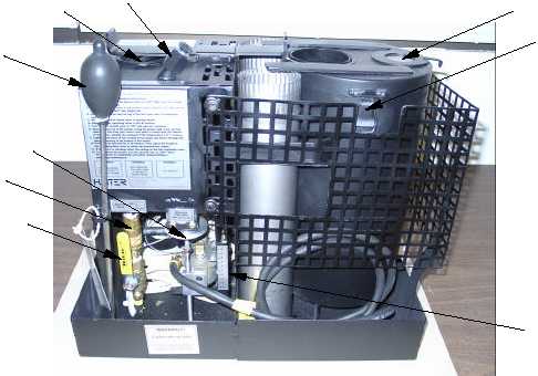
The following illustrations and tables show the location and function of each control and indicator on the
SHS and its associated equipment. Table 1 describes the controls and indicators for the SHS.
Table 1. SHS Controls and Indicators
KEY
ITEM
FUNCTION
1
AIR VENT/PRIMER PORT CAP
Allows air to enter the fuel tank during operation so that fuel is
able to flow freely through the fuel management system. The
primer port cap is removable so that fuel can be extracted from
the fuel tank for priming.
2
BURNER RATE CONTROL
Controls fuel flow by moving zero pressure regulator to desired
setting.
3
BURN RATE INDICATOR SCALE
A scale from 1 to 10 that indicates the relative burn rate of the
heater. One is the lowest setting and ten is the highest.
4
FUEL ON/OFF CONTROL
A ball valve that has an ON-OFF position. Controls fuel flow from
fuel tank to the regulating float valve.
5
LID ASSEMBLY SIGHT GLASS
Located on the top of the lid assembly, the sight glass allows
viewing of flame in burner.
6
FUEL CAP
Located on the top of the fuel tank, can be removed to gain
access to fuel tank for refueling.
7
LID ASSEMBLY LATCHES
Two latches located on either side of the lid assembly that
secure the lid assembly to the burner canister.
8
PRIMER BULB
Slender aluminum tube with rubber squeeze bulb that permits
fuel to be extracted from the fuel supply and injected into the
burner shell for priming.
9
FUEL QUICK DISCONNECT
Fuel quick disconnect fitting that allows an external fuel supply to
be connected to the heater.
1
3
4
2
5
6
7
8
9