
(1) Clean fuel control valve with an approved
cleaning solvent and dry thoroughly.
(2) Inspect unit for any signs of damage.
d. Adjustment. To check control valve fuel flow
rate, proceed as follows:
(1) Disconnect fuel control feed line (25, fig.
fuel is flowing to valve. Valve must be in a level
position .
(2) Turn control knob all the way open (HIGH)
and allow flow to stabilize. Check flow for one minute
by catching flow in 50 cubic centimeter graduated
container. Flow should be in accordance with rating
listed in paragraph 1-8 b (8), (9), or (10).
(3) Adjust high flow rate adjusting screw
Turn control knob counterclockwise to
increase and clockwise to decrease flow. Recheck flow
after adjusting.
(4) Turn control knob to LOW position
(FIRST MARK position on Models 441-4ABJ and 444-
4A) and allow flow to stabilize. Check the flow for one
minute by catching flow in container. Flow should be in
accordance with rating listed in paragraph 1-8b(8), (9),
or (10).
(5) Adjust low flow rate adjusting screw (fig.
and clockwise to decrease flow. Recheck flow after
adjusting.
(6) Replace fuel control feed line and check
for leaks.
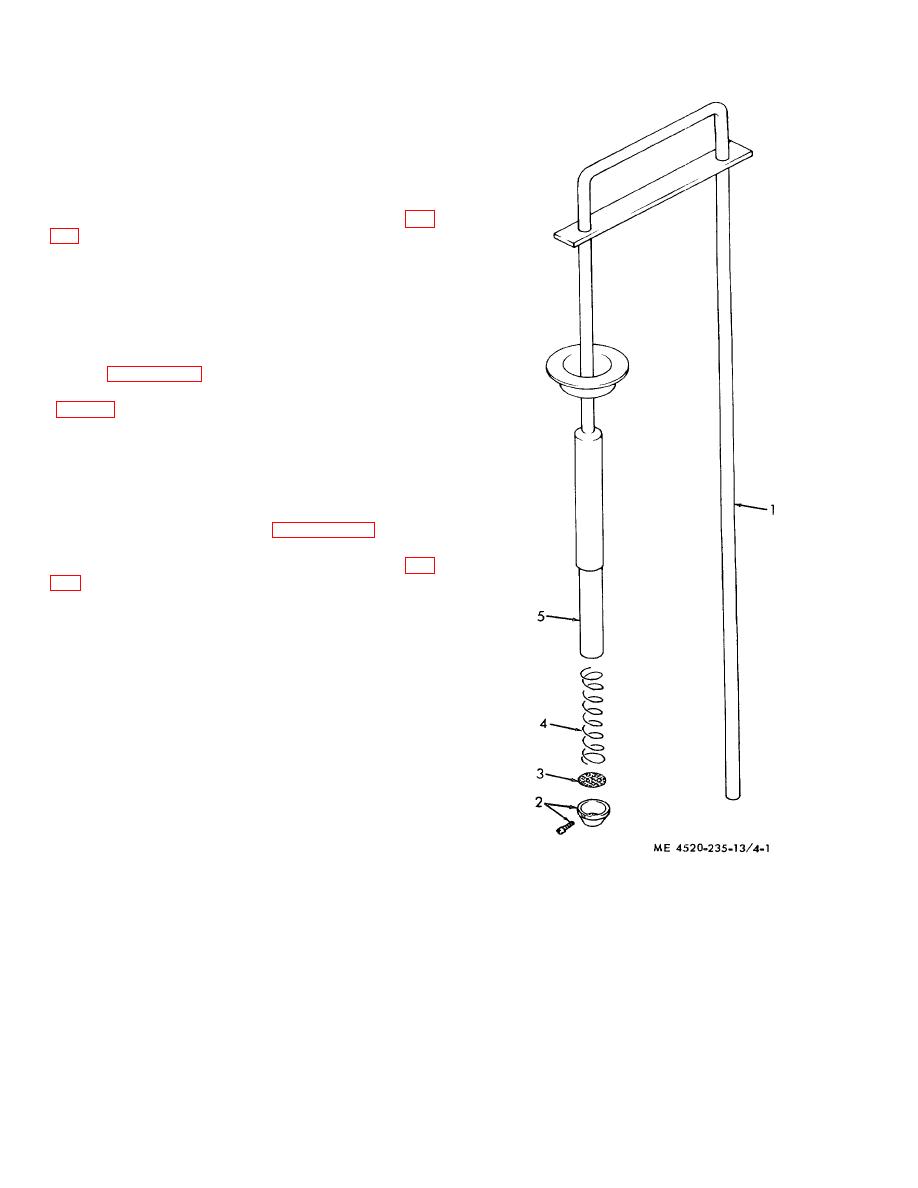
1.
Siphon barrel
2.
Bottom
3.
Screen
4.
Spring
5.
Plunger assembly
Figure 4-1. Siphon assembly, exploded view.
4-4
