
TM 5-4520-241-14
KEY
ITEM
KEY
ITEM
KEY
ITEM
B1
Ventilating motor
E1
S2
Toggle switch (HEATER-OFF-
B2
Combustion motor
HR1
Fuel heater
FAN)
C1
Capacitor, interference
HR2
Bimetal heater/sensor
S3
Flame switch
suppression
(Time delay)
S4
Thermal cutout switch
C2
Capacitor, interference
J2
ROOM THERMO receptacle
S5
Overheat thermostat switch
suppression
J4
EXTERNAL FUEL PUMP
S6
Overheat thermostat switch
CB1
Circuit breaker, 20 amps
RECEPTACLE
S7
Fuel thermostat switch
CR1
Rectifier (Fuel pump power
L1
Solenoid valve
S8
Safety switch
supply)
P1
Male plug (Control box)
T1
Ignition transformer
CR2
Rectifier (Time delay)
(see 2, fig. 4-15)
T2
Fuel pump power supply
DS1
Incandescent lamp (Red)
Q1
Transistor
DS2
Incandescent lamp (White)
S1
Switch, SPST (RESET)
T3
Time delay transformer
TS 4520-241-14/1-3
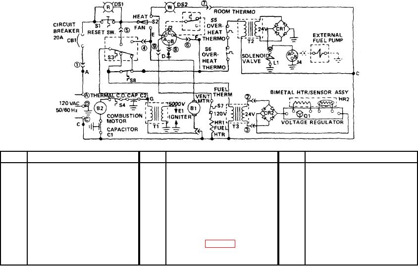
Figure 1-3. Circuit schematic diagram.
1-7