
TM 5-4520-241-14
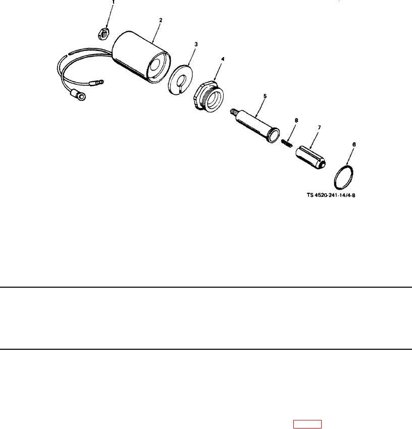
1.
Nut
5.
Stem
2.
Coil
6.
Preformed packing
3.
Washer
7.
Plunger
4.
Nut
8.
Spring
Figure 4-8. Solenoid assembly.
Table 4-2. Organizational Maintenance Troubleshooting - Continued
MALFUNCTION
TESTING OR INSPECTION
CORRECTIVE ACTION
5.
HEATER IGNITES, THEN STOPS, AND RED LIGHT COMES ON.
Step 1.
Check flame switch. Disconnect power plug and thermostat plug. Open access doors. When heat
exchanger is cool, there must be continuity from the brown wire to the green and the white/black
wires. When the heat exchanger is hot, there must be continuity from the brown wire to the orange
wire and the blue wire.
Disconnect power plug. Disconnect wires at flame switch, (8, fig. 4-9). It is normally possible to
remove the flame switch without removing the carburetor or burner head. Remove screws (1),
4-32