TM 5-4520-253-13
ACCESSORY ITEMS PROCEDURES INDEX
PROCEDURE
PAGE
Test/Adjust/Remove/lnstall Room Thermostat
3-120
Remove/install Side Heater Case Covers
3-123
Remove/Install Power, Fuel Pump, and Room Thermostat Plugs
3-124
T E S T / A D J U S T / R E M O V E / l N S T A L L R O O M T H E R M O S T A T
TEST EQUIPMENT: Volt ohmmeter
TOOLS: Tool kit, service, refrigeration unit
NSN 5180-00-596-1474
GENERAL SAFETY INSTRUCTIONS:
Power off.
TESTING:
1.
2.
3.
4.
5.
Death or serious injury could occur if precautions are not
taken when maintaining this equipment. Position HEATER-
OFF-FAN switch to OFF, remove power cable plug from
POWER RECEPTACLE, and ground capacitors Cl and C2
at end cover of combustion blower. Always have another
person standing by who is trained in electric shock first aid.
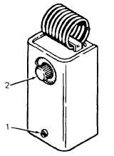
Disconnect thermostat cable from ROOM THERMO receptacle.
Remove screw (1) at bottom of thermostat cover and pull off
cover.
Slowly rotate adjustment knob (2) clockwise and counter-
clockwise. Thermostat should click as dial is rotated past
room temperature, as long as room temperature is within
thermostat range.
If click is not heard, check continuity across switch ter-
minals. Place probes of volt ohmmeter on switch termi-
nals. Again rotate adjustment knob. There should be
continuity when the thermostat is set above room tem-
perature by 2°F (1.1° C) or more. There should be no
continuity when it is set below room temperature by 2°F (1.1° C) or more.
If thermostat does not operate as described above, replace.
3-120


