TM 5-4520-253-13
REMOVE/INSTALL PC BOARD ASSEMBLY (CONT)
2.
3.
4.
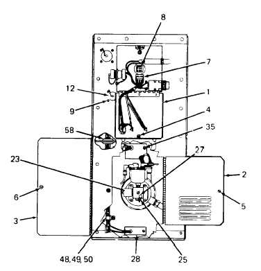
Disconnect control box harness plug (7) from PC board wiring receptacle (8). Depress locking tabs and pull
receptacle out of mounting hole from inside heater case.
Remove four screws (9), lock washers (10), and nuts (11) and lift out EXTERNAL FUEL PUMP RECEPTA-
CLE (12) from inside heater case. One screw (9), lock washer (10), and nut (11) also attaches dust cap and
chain (13) and ground wire (14). Retain dust cap and chain.
Remove four screws (15), lock washers (16), and nuts (17) and lift out POWER RECEPTACLE (18) from
inside heater case. One screw (15), lock washer (16), and nut (17) also attaches dust cap and chain (19) and
ground wire (20). Retain dust cap and chain.
NOTE
For Model UH-68G, PC board assembly may have been
replaced with PC board assembly for Model UH-68G1.
On Model UH-66G1, disconnect PC board assembly harness plug (8A) from receptacle (8 B).
NOTE
Tag all wires as they are disconnected.
On Model UH-68G, disconnect green and blue wires (21 and 22) from fuel solenoid (23). Disconnect orange
wire (24) from carburetor thermostat (25). Disconnect white wire (26) from carburetor heater (27).
Change 2
4-13