TM 5-4520-256-14
1-9. LOCATION AND DESCRIPTION OF MAJOR COMPONENTS.
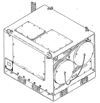
a. Left and Front Side. (Refer to Figure 1-2).
(1) Supply Air Duct. The supply air duct (1) moves the hot air from the heater unit to the shelter.
(2) Return Air Duct. The return air duct (2) brings return air back to the heater unit for reheating.
(3) Instruction Plates. The instruction plates (3) provide instructions for the operation of the heater unit.
(4) Fresh Air Damper. The fresh air damper (4), when opened, allows fresh air to be drawn into the heater unit and
used in the ventilating or fresh air heating mode.
(5) Control Panel. The control panel (5) contains the operator controls and indicators used during the operation of
the heater unit.
(6) Return and Supply Air Dust Covers. The return and supply air dust covers (6) prevents dust and debris from
entering the heater unit when the unit is not in operation.
(7) Power Cable. The power cable (7) is to be connected to a power source to operate the heater unit. Models H82
and H83 have different power cables.
Figure 1-2. Heater Unit, Front and Left Side
1-4 Change 3