TM 9-4520-257-12&P 0005 00
0005 00-16
2. Open the front base heater door (1), pull the priming cup (2) on the retainer wire (3) out of the heater
body base until the wire is fully extended, and set aside.
3. Remove the top heater shell (4) from the heater body base (8) by loosening the wing nuts on the bolt
and wing nut assemblies (21) and sliding them out of the brackets (22) on the top heater shell (4).
Set the top heater shell (4) aside. If not already done, remove all the components stored inside the
heater. (See WP 0009 00 for an inventory of all the components.)
4. Replace the burner shell assembly (5) in the heater body base (8). If necessary, rotate the burner
shell assembly (5) to ensure that the pipe nipple (6) aligns with the left side of the front base heater
door opening (7) in the heater body base (8). Pull the flow control burner hose (9) through the front
base heater door opening (7). The burner shell assembly (5) and adapter ring (10) welded to its top
must be level and fully engaged all around the circumference of the heater body base (8).
5. The superheater (11), burner cap assembly (12), and high fire ring (13) are all installed when
shipped. Ensure that these parts are in place as illustrated.
6. Insert the fuel flow control valve (14) into the bracket holder (15) on the heater body base (8).
7. Attach the free end of the flow control burner hose (9) to the flow control outlet (16) on the bottom of
the fuel flow control valve (14). To do this, pull back on the female QD fitting on the end of the flow
control burner hose (9), insert it on the flow control outlet male QD fitting, and release the female QD
fitting. Gently pull on the flow control burner hose to ensure the connection is secure.
8. Attach the female QD fitting on the fuel overflow hose (17) to the fuel overflow male QD fitting (18) on
the fuel flow control valve (14). To do this, pull back on the female QD fitting on the fuel overflow
hose (17), insert it on the fuel overflow male QD fitting (18) on the fuel flow control valve (14), and
release the female QD fitting. Gently pull on the fuel overflow hose to ensure the connection is
secure. Set the free end of the fuel overflow hose aside.
9. Connect the female QD fitting (19) on the fuel supply hose (23) to the fuel supply male QD fitting (20)
on the fuel flow control valve (14). To do this, pull back on the female QD fitting (19) on the end of
the fuel supply hose (23), insert it on the fuel inlet male QD fitting (20), and release the female QD
fitting (19). Gently pull on the fuel supply hose (23) to ensure the connection is secure. Set the free
end of the fuel supply hose (23) aside.
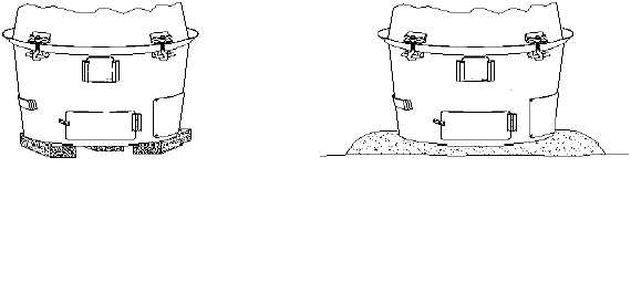
BRICKS
SAND
LEVELING THE H-45


