TM 9-4520-258-14
1-9. LOCATION AND DESCRIPTION OF MAJOR COMPONENTS - continued.
c. Heater Interior - continued. (Refer to Figure 1-4)
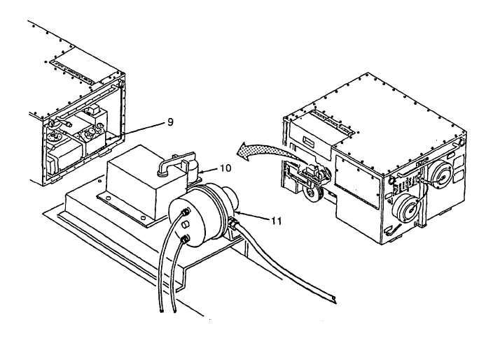
(9) Fuel Tank. The fuel tank (9) holds 14 gallons of fuel.
(10) Combustor Control Relay Assembly. The combustor control relay assembly (10) provides for safe
operation/control of the burner assembly.
(11) Air Pressure Switch. The air pressure switch (11) detects air flow to the heat exchangers. It allows power to
the combustor control relay assembly.
Figure 1-4. Heater Interior (Sheet 3 of 3)
1-10