
TM 9-4520-271-14
0053 00
ASSEMBLY
Continued
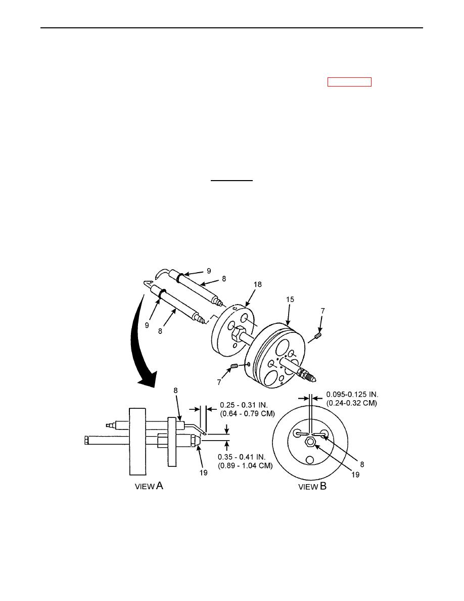
14. Insert two electrodes (8) into baffle (18) and block (15). Ensure that O-rings (9) (items 38, WP 0062 00) are inserted
into baffle 0.12 to 0.18 inch (0.31 to 0.46 cm) from outer surface of baffle.
15. Install two setscrews (7). Do not tighten.
16. Position tips of two electrodes (8) 0.25 to 0.31 inch (0.64 to 0.79 cm) in front of nozzle (19) and 0.35 to 0.41 inch (0.89
to 1.04 cm) above nozzle discharge port (View A).
17. Torque two setscrews (7) to 10 to 15 lb-in. (1.1 to 1.6 Nm).
CAUTION
Use care when bending electrode tips or damage may result.
18. Carefully bend tips of two electrodes (8) to adjust gap to 0.095 to 0.125 inch (0.24 to 0.32 cm) (View B).
19. Check position of two electrodes (8). Repeat steps 17 thru 19 as required.
20. Ensure that position of two O-rings (9) is 0.12 to 0.18 inch (0.31 to 0.45 cm) from nozzle (19) side of baffle (18).
0053 00-7
