
TM 9-4520-272-14&P
0040 00
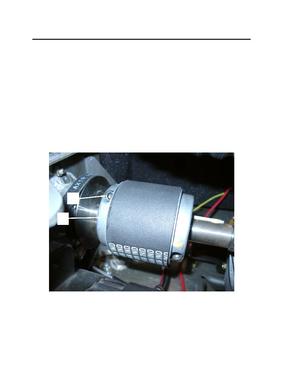
19. Slide the right portion (6) of the coupling assembly left along the engine drive shaft (7) until the gap
between the right edge of the rubber section and the ridge (12) of the right portion (6) is 1/8 inch. The
gap is provided to allow for the expansion of the coupling due to heating.
20. Ensure that the "teeth" (11) on the center rubber section (8) mate properly with the "teeth" (12) on the
left and right portion of the coupling assembly.
21. Using a torque wrench equipped with a 1/2 inch socket to 1/4 inch hex key adapter, install and torque
the hex head cap screws (1 and 5) on the left (2) and right (6) portions of the couplng assembly to 22
ft-lbs.
22. Close the engine access door.
NOTE
Allow 20 minutes for the retaining compound to set up before proceeding to next step.
Failure to do so will prevent proper set up of the retaining compound.
23. Operate the heater for one hour. Check for "walk" left or right of the coupling assembly. Check the
torque on the hex head cap screws (1 and 5) and verify that it is still 22 ft-lbs. Re-torque as required.
1
2
0040 00-3
