T M 9 - 4 9 3 1 - 3 8 1 - 1 4 & P - 2
FRAME 15
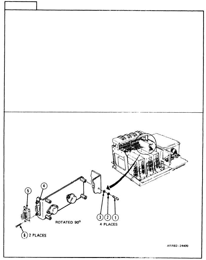
Remove Circuit Card Assembly A2:
1.
Unscrew two screws (1) holding receptacle connector P1 (2) to circuit card assembly
(3) using flat tip screwdriver.
2. Unscrew and take out four machine screws (4), lockwashers (5), and flat washers (6)
from circuit card assembly (3) with cross tip screwdriver. Get rid of Iockwashers
(5).
3. Lift out and position circuit card assembly (3) so connector P1 (2) is exposed.
4 . T a k e
5.
Look
aside
off connector P1 (2) from circuit card assembly (3).
at circuit card assembly (3) for cracks or bends. If bad, turn in. If OK, set
for later use.
Follow-on Maintenance:
NOTE: To install circuit card assembly A2, refer to task 19.
TASK 6 ENDS HERE
Volume IV
2-234
Para. 2-9, Task 6