
TM 5-4520-208-15
gasoline engine power unit when the engine
b. Power Units. The Model BT400-40 heat-
is used to drive the heater.
er is supplied with two power units: one is
a Military Standard gasoline engine, Model
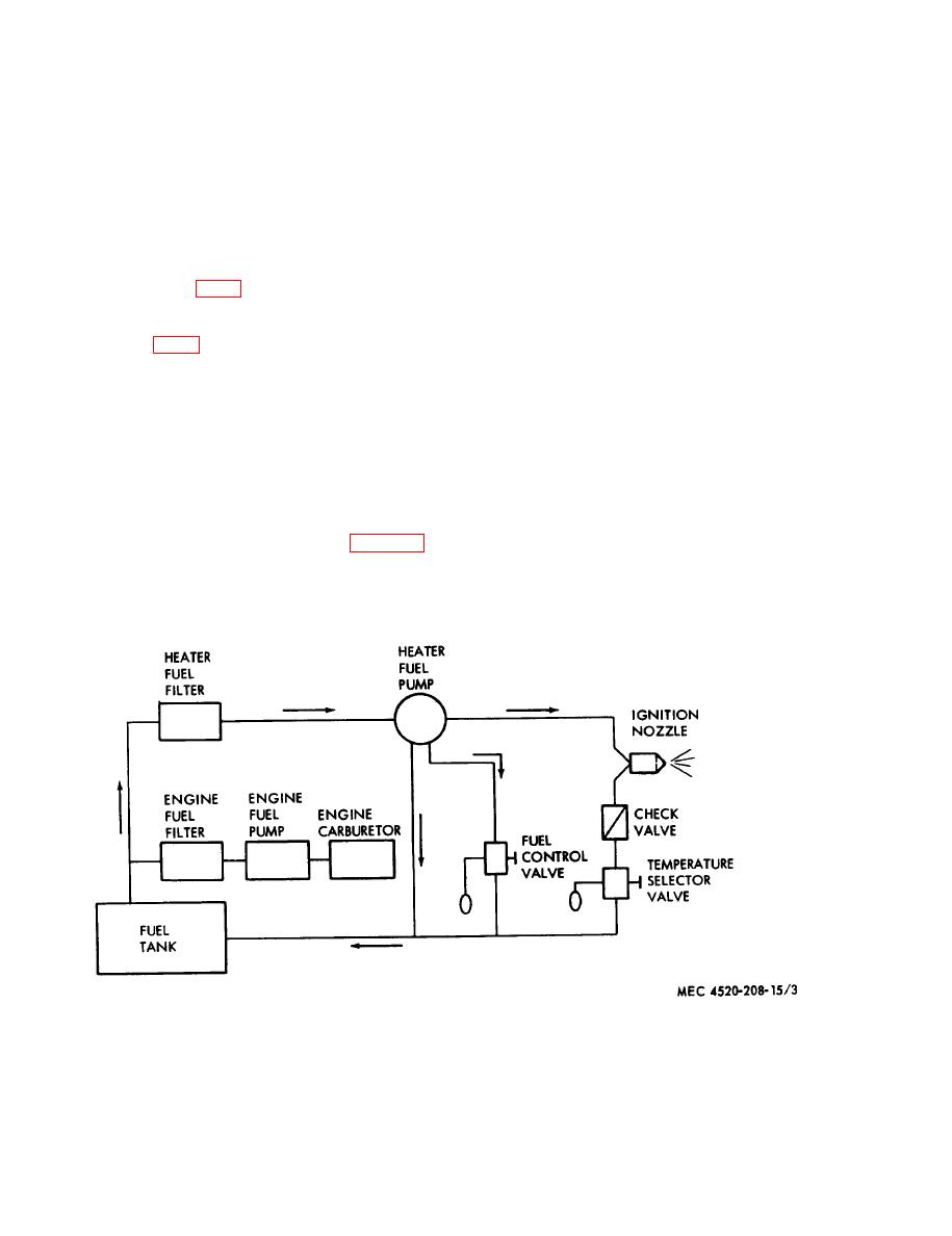
(1) Fuel tank. The 16-gallon fuel tank
1A08-III; the other a 2-horsepower, 208-220
is suspended by straps in the base
volt, 60-cycle, 3-phase alternating current elec-
of the heater and is removable. Fuel
tric motor. The Model BT40040-1 heater is
is drawn from the tank through
supplied with only the Military Standard gas-
automotive-type filters and delivered
oline engine, Model 1A08-III. Each power
to the gasoline engine power unit
unit supplies all the air necessary for opera-
and the heater fuel pump.
tion of the heater. Air is drawn through the
(2) Engine fuel system. Fuel from the
air inlet door (fig. 1), passes through and
tank is drawn through the filter by
around the heat exchanger, and is discharged
the engine fuel pump. The fuel
through ducts mounted on the duct adapter
passes through the engine fuel filter
assembly (fig. 2). Both power units have a
to the carburetor and is ignited by the
coupling attached to the drive shaft. The drive
engine. A quick-disconnect coupling
coupling is connected to the driven coupling
is supplied on the fuel line at the
by a flexible rubber sleeve which mates the
engine fuel line at the engine fuel
two. The driven coupling drives the heater
filter inlet line to facilitate removal
fan and, through a pulley which is an
of gasoline engine.
integral part of the driven coupling, a V-belt.
(3) Healer fuel pump. The belt-driven
The belt drives the fuel pump mounted on
heater fuel pump draws fuel through
the right side and the heater ignition magneto
the filter and delivers fuel at a con-
on the left side of the power unit.
stant high pressure to the nozzle. The
pump operates continuously when
power unit is in operation. Unused
supplies gasoline to the heater and to the
Figure 3. Fuel system, schematic diagram.
4
