
TM 10-4500-200-13
Section III. MOVEMENT TO A NEW WORK SITE
assembly.
a. Dismantling.
(5) If unit is being moved to another space in the
same area, it can be hand carried.
(1) Remove stack and separate into sections.
(2) Remove fuel tank from heater.
b. Reinstalled After Movement. Reinstall the im-
mersion heater at the new work site as directed in
(3) Remove heater from tank.
(4) Clean soot from pipe sections and burner
Section IV. CONTROLS
5-8. General
Move the gate to one side when pre-heating the flue
and close it after about 2 minutes.
This section describes the various controls and pro-
vides the operator/crew sufficient information to in-
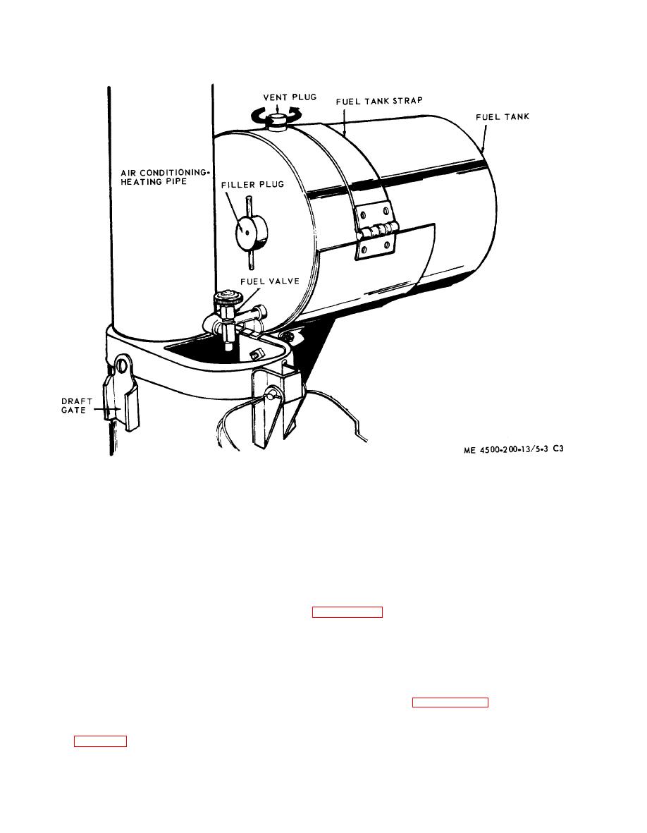
b. Fuel Valve. The fuel valve is located on a short
sure proper operation of the immersion heater. Con-
pipe nipple extending from the fuel tank. Adjust the
valve as described in paragraph 5-11.
trols are identical for all models.
c. Vent Plug. The vent plug is located on top of the
5-9. Controls
fuel tank. When preheating the flue, unscrew the
Refer to figure 5-3 for the location of each control.
vent plug as far as possible without forcing it and
a. Draft Gate. The swing type draft gate is located
leave it unscrewed as long as the heater is in opera-
on the side of the flue compartment near the top.
tion.
