TM 10-4520-261-12&P
SPACE HEATER ARCTIC (SHA)
0004 00
CONTROLS, INDICATORS, AND LABELS/INSTRUCTION PLATES
0004 00-2
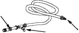
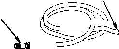
FUEL SUPPLY AND OVERFLOW HOSES
Table 2 describes the controls and indicators for the Fuel Supply and Overflow hoses.
Table 2. Fuel Supply and Overflow Hose Controls and Indicators
KEY
CONTROL AND INDICATOR
FUNCTION
1
Female QD Connector fuel supply hose
Connects fuel supply to Fuel Flow Control Valve
2
“T” connector with petcock
Permits fuel to be drained into cup for priming
3
Male QD connector fuel supply hose
Connects fuel supply hose to fuel can gravity feed adapter
4
Female QD connector fuel overflow hose
Connects to Fuel Flow Control Valve to permit excess fuel to
drain
5
Open end of fuel overflow hose
Placed outside of shelter on downslope to permit any overflow
fuel to drain
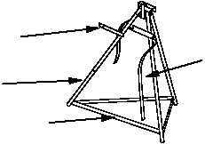
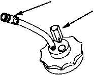
FUEL CAN STAND (OPTIONAL) AND GRAVITY FEED ADAPTER
Table 3 describes the controls and indicators for the Fuel Can Stand. (The fuel can stand is available as
an Additional Authorized Item as detailed in WP 0045.)
Table 3. Fuel Can Stand (optional) and Gravity Feed Adapter Controls and Indicators
KEY
CONTROL AND INDICATOR
FUNCTION
1
Fuel Can Stand Leg Assembly
Provides stable tripod to support fuel can
2
Fuel Can Supports
Supports fuel can when in feed position
3
Fuel Can Strap
Straps fuel can to stand
4
Fuel Can Stand Stabilizer Straps
Permits proper spacing of fuel can stand leg assembly
5
Gravity Feed Adaptor Female QD Connector
Connects fuel supply to fuel supply hose
6
Gravity Feed Adaptor Automatic Vent Valve
Allows air to vent into fuel can, permitting proper fuel flow
1
2
3
2
4
5
4
1
3
5
6


