
TM 5-4520-240-14
c. Disconnect the time delay assembly leads at ter-
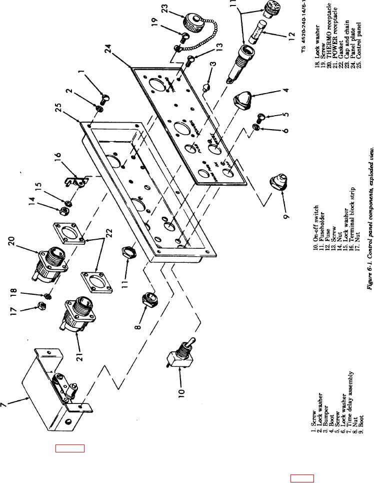
control panel; remove the time delay assembly and
minal block TB1 (fig. 1-4), and unsolder the leads at ter-
remove nut (8).
minal block strip (16, fig. 6-l), fuseholder F1, ON-OFF
d. If the ON-OFF switch (10) is defective, tag and un-
switch S1, and thermostat receptacle J2. Remove bum-
solder the two red and two violet leads from the switch.
pers (3). Unscrew the boot (4) and remove it from the
Refer to the wiring diagram (fig. 1-4). Unscrew the boot
RESET switch. Remove the two screws (5) and lock
(9) and remove the ON-OFF switch from the back of the
washers (6) securing the time delay assembly (7) to the
control panel
6-2