TM 5-4520-240-14
WARNING
sleeve (11) onto the thermocouple (13), and insert the
thermocouple into the heat exchanger. Tighten the nut
The ignition system of this space
to seat the compression sleeve onto the thermocouple.
heater contains dangerous voltages
(2) Install the grommet (10) into the hole in the
which can cause severe electrical
heat exchanger housing.
shock. Be sure to disconnect the power
(3) Form the thermocouple lead to make a loop and
then connect the end of the lead to the thermocouple
plug before repairing the heater.
(1) Disconnect the power plug and remove the top
(4) Install the warm air louver (fig. 4-4) and top
and side cover panels.
and side cover panels. Connect the power plug and
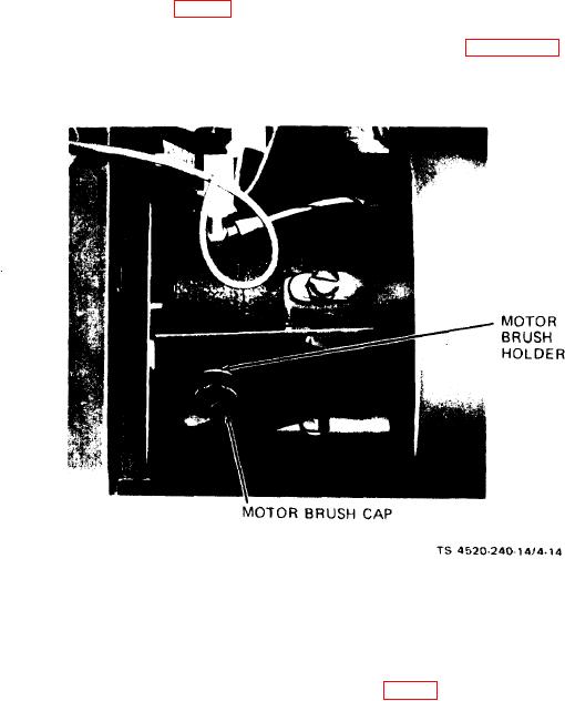
(2) Refer to figure 4-14, and remove the motor
check heater for proper operation.
brush caps. Remove the motor brushes from the brush
4-27. Motor Brushes.
holders.
a. Removal.
Figure 4-14. Motor brush installation.
the power plug. Start the heater and check for proper
b. Inspection.
operation.
(1) Inspect the wear faces of the brushes for signs
of scoring, uneven wear, burning, pitting, or other
4-28. Room Thermostat.
damage. Scored or unevenly worn brushes indicate that
a. Check the thermostat operation by operating the
the motor armature is defective. Report the condition
knob (fig. 2-2) from one extreme to the other, checking
to direct support maintenance.
that electrical continuity is made as the knob position
(2) Replace the brushes if the brush lead is broken,
indicates room temperature and below, and that con-
or if the brushes are worn to less than 5/16 inch long.
tinuity is broken above room temperature.
b. No repair is authorized for the room thermostat.
c. Installation
Replace a defective thermostat.
(1) Align the curve of the brush wear face with the
c. The thermostat may be cleaned by removing the
curvature of the motor armature commutator, and in-
cover and wiping away accumulations of dust and lint
stall the brushes in the brush holders. Reinstall the
with a soft-bristle brush. Check that all wiring connec-
brush caps.
tions are tight and reinstall the cover.
(2) Reinstall the top and side covers and connect
4-22

