
TM 5-4520-241-14
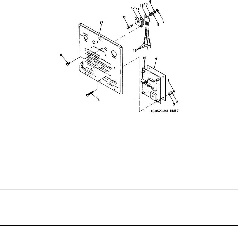
1.
Nut
10.
Shoulder washer
2.
Lock washer
11.
Screw
3.
Flat washer
12.
Heat sink
4.
Label
13.
Transistor
5.
Screw
14.
Insulator
6.
Screw
15.
Wires
7.
Nut
16.
PC board
8.
Lock washer
17.
Control box cover
9.
Washer
Figure 5-7. PC Board and transistor installation.
Table 5-1. Direct Support and General Support Troubleshooting - Continued
MALFUNCTION
TESTING OR INSPECTION
CORRECTIVE ACTION
4 - Continued
Turn off and disconnect the power. Reconnect the brown lead to terminal strip terminal G, and
replace parts.
If the PC board or transistor must be replaced, proceed as follows:
5-16