
TM 5-4520-241-14
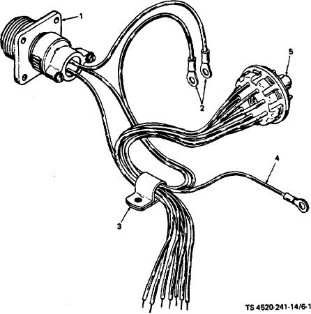
(3) Remove the black lead (4) from the circuit breaker. Pull out male plug (5).
1. Room thermostat receptacle
4. Black lead
2. Green leads
5. Male plug
3. Clamp
Figure 6-1. Control box wiring harness.
(4) Remove the red, yellow, white, blue, orange, and two violet wires from the PC board by scraping away the
insulating material and unsoldering. Pull the harness and room thermostat receptacle out of the control box.
(5) Unsolder the black/white, green, and violet wires from the room thermostat receptacle.
(6) Unsolder the nine wires from the male plug by applying a soldering iron to the tip of the pins and pulling gently
on the wires until they can-be removed easily.
6-2