
TM 5-4520-241-14
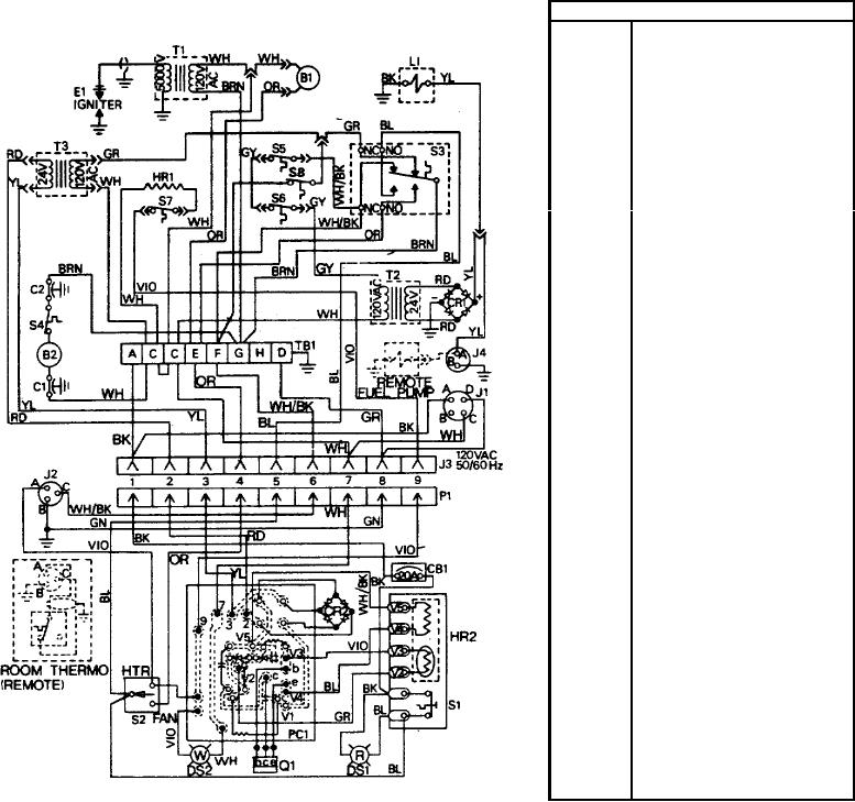
KEY TO DIAGRAM
B1
Ventilating motor
B2
Combustion motor
C1
Capacitor, interference
suppression
C2
Capacitor, interference
suppression
CB1
Circuit breaker, 20 amp
CR1
Rectifier (Fuel pump power
supply)
CR2
Rectifier (Time delay)
DS1
Incandescent lamp (Red)
DS2
Incandescent lamp (White)
E1
HR1
Fuel heater
HR2
Bimetal heater/sensor
(Time delay)
J1
POWER RECEPTACLE
J2
ROOM THERMO
receptacle
J3
Female receptacle
J4
EXTERNAL FUEL PUMP
RECEPTACLE
L1
PC1
PC bad assembly
P1
Male plug (Control box)
Q1
Transistor
S1
Switch, SPST (RESET)
S2
Toggle switch
(HEATER-OFF-FAN)
S3
Flame switch
S4
Thermal cutout switch
S5
Overheat thermostat switch
S6
Overheat thermostat switch
S7
Fuel thermostat switch
S8
Safety switch
TB1
Terminal board
(Terminal strip)
T1
Ignition transformer
T2
Fuel pump power
supply transformer
T3
Time delay transformer
TS 4520-241-14/6-2
Figure 6-2. Wiring diagram.
(1) Disconnect power plug. Remove the control box and disconnect male plug. Install a jumper from pin 1 to pin
6 in the female receptacle in the heater case.
(2) Open access doors and disconnect the brown lead to the flame switch at terminal strip terminal G. Connect
the power plug and measure voltage at pins 2 and 3 of the female receptacle. Voltage should be 23 to 30 VAC. If it is
not, replace the time delay transformer and retest.
(3) Remove the jumper installed in the female receptacle in step (1). Plug the control box into the female
receptacle and reinstall the control box on the front of the heater case. Set the room thermostat above ambient
temperature to ensure that its contacts are closed.
6-4