
TM 5-4520-241-14
Corning No. 340, or equivalent) to adjacent surfaces of transistor and heat sink. Assemble them with the insulator (13) in
between, and secure with attaching hardware.
(2) Cut new wires to length and slide a short length of heat shrink tubing onto each wire. Using a heat sink on
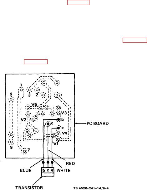
the transistor leads, solder the wires to the transistor as shown in figure 6-4, and shrink the tubing over the connections
(3) Solder the transistor wires to the PC board as shown, and spray the connections with moisture repellent
conforming to MIL-V-173 (Columbia Technical Corporation, Humi-Seal No. 1A27, Class A, or equivalent).
(4) Preassemble the time delay assembly before installing the PC board and transistor. Install reset switch (25)
and bimetallic heater/sensor (33), and solder the wires to terminal strip (37) as shown in figure 6-5. Use rosin core
electrical solder.
(5) If the PC board and transistor have been replaced as an assembly, install a new assembly by resoldering
wires to the same holes in the board. Refer to figure 6-5 for connections. Use only rosin core electrical solder.
Figure 6-4. Transistor connections.
6-9