
TM 5-4520-241-14
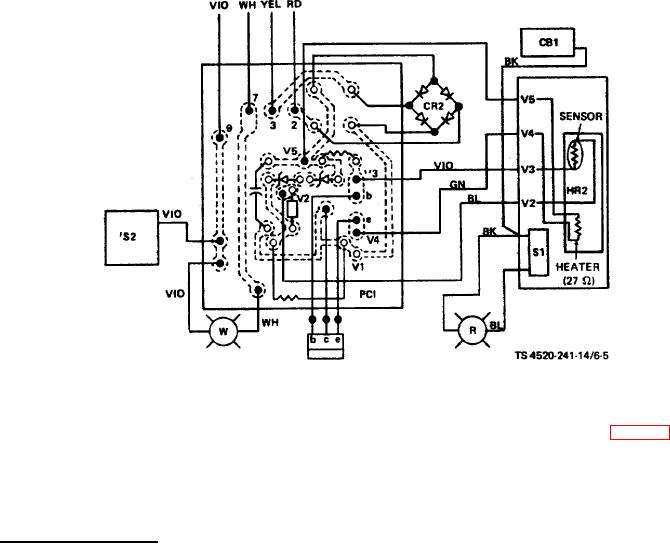
Figure 6-5. Control box wiring.
(6) Reassemble the remaining parts of the control box cover. Before installing label (4, fig. 6-3) over the PC
board foil side, spray all connections on the PC board and time delay terminal strip with moisture repellent conforming to
MIL-V-173 (Columbia Technical Corporation, Humi-Seal No. 1A27, Class A, or equivalent).
(7) If the bimetallic sensor/heater has been replaced, check the time delay adjustment after installation.
e. Time Delay Adjustment. Adjustment of the time delay is not a normal maintenance adjustment, but may be
required after replacement of the bimetallic heater/sensor. Adjust as follows:
(1) Connect the control box male plug to the female receptacle on the heater case. Attach the control box by
engaging the two stud turnlock fasteners in the control box.
(2) Leave open the control box cover. Disconnect the yellow lead from the output of the fuel pump power supply
transformer so that no power is applied to the carburetor solenoid valve or to the external fuel pump. Disconnect the
brown lead at terminal strip terminal G to disconnect the ignition transformer.
(3) Connect the power plug. Press the RESET button to clear the switch. Using a stopwatch or a clock with a
sweep second band, move the HEATER-OFF-FAN switch to HEATER and start timing.
6-10