TM 5-4520-253-13
l N S P E C T / T E S T / R E M O V E / l N S T A L L S A F E T Y T H E R M O S T A T S A N D F L A ME
S W I T C H A N D B R A C K E T A S S E M B L Y ( C O N T)
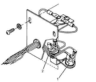
2. Test flame switch and bracket assembly for
continuity.
a. Disconnect red and violet wires from
flame switch (1). Using volt ohmmeter,
place one probe against each terminal of
flame switch (1). Meter should indicate
b.
c.
d.
e.
f.
g.
zero resistance.
Heat bottom of flame switch (1) to 130’ F
(54° C) and place probes on terminals.
Switch should snap (open) and meter
should indicate infinite resistance.
Connect red and violet wires to flame
switch (1).
Disconnect red and brown wires from flame switch (2). Using volt ohmmeter, place one probe
against each terminal of flame switch (2). Meter should indicate infinite resistance,
Heat bottom of flame switch (2) to 130° F (54° C) and place probes on terminals. Switch
should snap (close) and meter should indicate zero resistance.
Connect
If either
red and brown wires to flame switch (2).
flame switch (1 or 2) is defective, replace flame switch and bracket assembly.
REMOVAL:
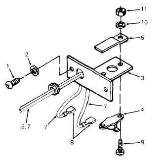
1. Remove lower overheat thermostat as follows:
a. Remove two screws (1) and lock washers
(2) at thermostat mounting bracket (3)
and lift out bracket and thermostat (4).
Thermostat is covered by shield (5).
b. Disconnect red/white and grey wires (6 and
7) from thermostat (4) at quick disconnect
terminals (8).
c. Remove two screws (9), lock washers (10),
and nuts (11) securing thermostat (4) to
mounting bracket (3). One screw/lock
washer/ nut combination secures shield (5)
to lower thermostat. Retain shield for
reassembly. Lift off thermostat (4).
3-107


