TM 54520-253-13
lNSPECT/REMOVE/lNSTALL ROOM THERMOSTAT RECEPTACLE (CONT)
REMOVAL:
1.
Remove screw (1), lock washers (2 and 3), and nut (4) attaching ground wire (5).
MODEL UH-68G1
MODEL UH-68G
2.
3.
4.
5.
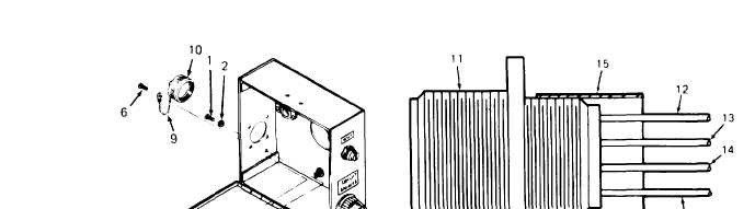
Remove four screws (6), lock washers (7), and nuts (8). One screw (6) also attached chain (9) of dust
cover (10), Retain chain and dust cover.
Pull room thermostat receptacle (11) out of mounting hole from inside control box.
For Model UH-68G, control box harness wires connected to room thermostat receptacle (11) are
potted to the receptacle. To remove receptacle, cut orange wire (12), green harness wire (13), violet
wire ( 14), and ground (green) wire (5) as close to receptacle as possible. Discard receptacle. Harness
wires are long enough to allow cutting close to receptacle and installing new receptacle.
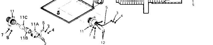
For Model UH-68G 1, control box harness wires connected to room thermostat receptacle (11) are
soldered and mechanically sealed to the receptacle. To disassemble and remove receptacle, unscrew
endbell (11A) from room thermostat receptacle and slide it back over the wires (5, 12, 13, and 14).
Pull back ferrule (11B) and grommet (11C) to expose soldered ends of the wires. Unsolder or cut
wires as close to receptacle as possible.
INSTALLATION:
1.
Strip 1/4 inch (6.35 mm) of insulation from the cut ends of orange wire (12), green harness wire (13),
violet wire (14), and ground (green) wire (5).
2.
For Model UH-68G1, thread wires (5, 12, 13, and 14) through endbell (11A) and ferrule (11B).
Thread the stripped end of each wire through grommet (11C) as follows:
a.
SIide out orange wire (12) through grommet (11C) opening A.
b.
Slide out green harness wire (13) and ground (green) wire (5) through opening B.
c.
Slide out violet wire (14) through grommet opening C.
3-40
Change 2