TM 5-4520-253-13
lNSPECT/REMOVE/lNSTALL POWER RECEPTACLE AND EXTERNAL FUEL PUMP
- R E C E P T A C L E ( C O N T )
2. Prepare POWER RECEPTACLE (4) as follows:
a.
b.
c.
Strip 1/4 inch (6.35 mm) of insulation from cut
ends of black and white wires (5 and 6) and
ground (green) wire (7).
For Model UH-68G1, thread wires (5, 6, and 7)
through endbell (4.1) and ferrule (4.2). Thread
the stripped end of each wire through grommet
(4.3) as follows:
(1)
(2)
(3)
Slide black wire (5) through opening A of
grommet (4.3).
Slide white wire (6) through opening C of
grommet.
Slide ground (green) wire (7) through open-
ing D of grommet.
Solder wires (5, 6, and 7) to receptacle termi-
nals as follows:
(1) Black wire (5) to terminal A.
(2) White wire (6) to terminal C.
(3) Ground (green) wire (7) to terminal D.
For Model UH-68G, pot wires as described in
step 3, following.
For Model UH-68G1, push grommet (4.3) into
rear of receptacle (4), ‘seat ferrule (4.2) over
grommet, and tighten endbell (4.1) to threads
on rear of receptacle.
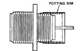
3. For Model UH-68G, the procedure for potting wires to POWER RECEPTACLE and EXTERNAL FUEL
RECEPTACLE is the same for both receptacles. Proceed as follows:
a. Make potting rim around receptacle using tape.
Rim must project beyond receptacle around
wires 1/4 inch (6.35 mm) or more.
b. Fill rim with sealant and allow 8 hours to cure.
4. Install EXTERNAL FUEL PUMP RECEPTACLE (11) inmounting hole from inside heater case. Secure recep-
tacle using four screws (8), lock washers (9), and nuts (10). Attach terminal end of ground wire (14) to one
screw/lock washer/nut combination during this step.
Change 2
3-63
d .
e.