TM 9-4520-251-14
4-41 DRIVE BELT (CONT)
Location/Item
Action
Remarks
REMOVAL
NOTE
It is assumed that the engine assembly has been removed as described in
paragraph 4–21. For this procedure, the engine assembly only needs to be
removed enough to cause separation of the coupling.
3.
Drive belt
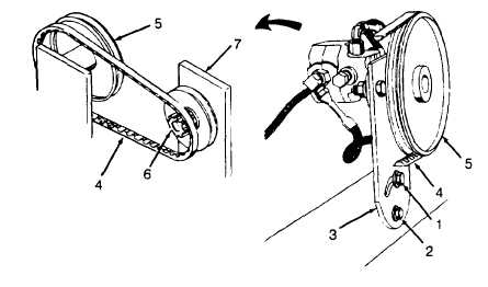
Loosen cap screws (1 and 2) and pivot fuel pump
bracket (3) to relieve tension on drive belt (4).
Remove drive belt from pulley (5). Remove drive
belt from pulley (6) on fan and hub assembly (7).
INSTALLATION
4.
Drive belt
Install drive belt (4) on pulleys (5 and 6) and
adjust tension to 1/4 to 1/2 inch (6.35 to
12.7 mm) deflection with 10 lb (4.5 kg) pres-
sure at midpoint
5. Cap screws
Tighten cap screws (1 and 2) firmly.
NOTE
Install engine assembly as described in paragraph 4-21
4-101

