T M 9 - 4 9 3 1 - 3 8 1 - 1 4 & P - 2
FRAME 4
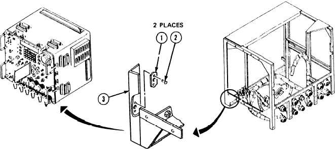
Replace Plain Nut Plates:
NOTE
Read paragraph 2-4 on replacing plain nut plates before
doing any work.
Soldier A:
1. Look at plain nut plates (1). lf bad go to step 2. lf OK, go to follow-on
maintenance and TASK 1 ENDS HERE.
Soldier A:
2. Takeout two solid rivets (2) holding nutplate (1) with 3/32-inch punch
and hammer. Get rid of rivets and nutplate.
Soldier A:
3. Line upholes in new nutplate (1) and chassis (3).
Soldier A,
Soldier B:
4. Put two new rivets (2) in nutplate (1) and chassis (3).
Follow-on Maintenance:
1. Install front panel connectors bracket; refer to para. 2-13, task 3.
2. Install electronics unit (EU); refer to para. 2-12, task 2.
3. Install electrical load bank A5; refer to para. 2-11, task 18.
4. Install power module A6; refer to para. 2-9, task 23.
5. Install lDU assembly A2; refer to para. 2-8, task 19.
6. Install digital subsystem assembly A3; refer to para. 2-7, task 18.
7. Install panel assembly A1; refer to para. 2-6, task 25.
8. Install thermal system test controller; refer to para. 2-5, task 8.
9. Install thermal system test controller case cover; refer to volume 1, para. 4-18.
END OF STRUCTURAL CHASSIS MAINTENANCE
Volume IV
Para. 2-14, Task 1
2-335/(2-336 blank)


