T M 9 - 4 9 3 1 - 3 8 1 - 1 4 & P -2
F R A M E 6
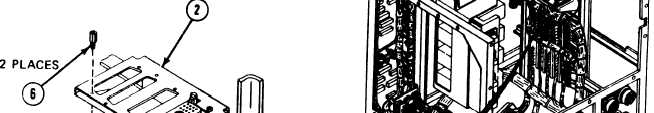
Install Connector:
NOTE
Use this procedure to install connectors
W14J1. Connector W13J2 (1) is shown.
1.
Line up connector (1) on bracket (2).
2. Screw in and tighten two hexaqon Plain nuts (3).
W3J2, W17J1, and
flat washers (4). new Iockwashers
(S), and electrical jack socket (6) with 3/16-inch single socket spinner socket
wrench and 3/16-inch combination wrench.
Follow-on Maintenance:
1. Install IDU assembly A2; refer to para. 2-8, task 19.
2. InstalI power module A6; refer to para. 2-9, task 22.
3. InstalI panel assembly A1; refer to para. 2-6, task 25.
4. InstalI thermal system test controller; refer to para. 2-5, task 8.
5. install thermal system test controller case cover; refer to volume 1, para. 4-18.
END OF FRONT PANEL CONNECTORS BRACKET MAINTENANCE
Volume Iv
2-330
Para. 2-13, Task 3