TM 10-4520-262-12&P 0037 00
0037 00-7
REPLACE
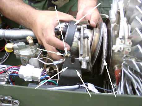
1. To replace the burner assembly, remove the burner as decribed in the section of this work
package entitled REMOVE.
2. Mount the new burner assembly (1) on burner bracket (2) by sliding screws (3) into burner
bracket slots (4). Ensure that the flame sensor is positioned at the top.
3. Ensure that the fiberglass rope is in place in the groove on the front surface of the TEG flange.
Ensure that the mantle is in place inside the TEG. Move the burner assembly (1) toward the
mantle and TEG (5) and seat it against and aligned with the TEG. Tighten the two wings nuts (6)
securely.
4. Install new graphite ribbon seal (7) around the TEG flange and the burner flange. Center the
graphite ribbon tape so that it equally overlaps both flanges. Overlap the ends of the graphite
ribbon tape by approximately 1 to 1 1/2 inches.
5. Install and secure the burner assembly (2) to the TEG with the V-clamp with nut (8). Do not rotate
the clamp once it is over the graphite tape. Tighten the two nuts securely.
6. Connect fuel line (13) to burner assembly (2) at fitting (14).
7. Connect combustion air inlet pipe (9) to burner assembly (2) using hose clamp (10). Tighten
clamp securely.
8. Connect the flame sensor connector (11) and connect the wire to the glow plug (12).
9. Reconnect ground wires (15 and 16).
3
4
2
1
5
6


