TM 10-4520-262-12&P 0037 00
0037 00-2
3. Disconnect fuel line (2) extending from the fuel pump (3) to the burner assembly (4) at fitting (5).
Carefully collect fuel which may spill from the hose. Wipe up any spilled fuel.
4. Tag and disconnect wire from flame sensor (6) and wire from glow plug (7).
5. Tag and disconnect the two ground wires (8 and 9).
6. Disconnect combustion air inlet duct (10) by loosening hose clamp (11) and sliding the clamp up
the duct. Pull the combustion air inlet duct off the burner assembly air inlet and move off to the
side.
7. Loosen the two wing nuts (12) on either side of the burner assembly bracket. Lift and pull burner
assembly (4) up out of the burner bracket and away from TEG (13) (Note that this will tear the
graphite ribbon tape and is normal; new graphite ribbon tape will be installed when the burner is
replaced). When the screws have cleared slots in burner bracket (14), lift out burner assembly (4)
and place on suitable work surface.
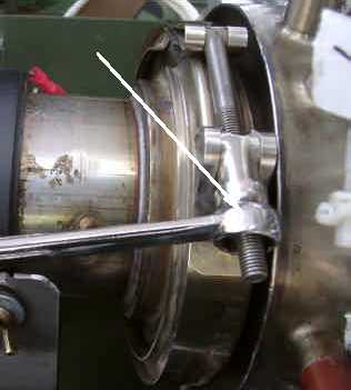
8. Clean any residual graphite ribbon tape from the TEG flange (13), burner assembly flange (15),
and the inside of the burner to TEG V-clamp (16).
9. Remove the three nuts and lockwashers (17), and quick connect tab (18) and set aside.
Disassemble the burner assembly into its separate components.
1


