TM 10-7310-241-12&P
4-22.6 Change 1
4-16.1 REPLACING THE CONTROL PANEL ASSEMBLY FOR MODEL 471012 (Continued)
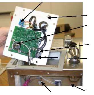
g. Inspecting the Circuit Board.
(1) Remove the control panel (Subparagraph 4-16.1a, steps (1) thru (4)).
(2) Check the circuit board wiring diagram to determine if all the wires are correctly connected
and securely attached.
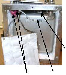
(3) Ensure that the thermistor mounted to the base (1) of the main container (2) is connected to the circuit
board location marked "BASE", and the thermistor mounted to the side (3) of the main container (2)
is wired to the circuit board location marked "SIDE".
(4) Ensure the gray thin isolator (4) is sandwiched between the black power transistor (5) and the
control plate (6) and that it is centered. Ensure the power transistor (5) mounting screw is tight.
(5) If not, conduct a continuity check on the wires that connect the switch (7) and the receptacle (8) to
the circuit board. Also, ensure there is continuity between the locations on the circuit board where
the thermal switch (9) wires are attached.
h. Replacing the Circuit Board.
NOTE
The circuit board is supplied with the thermistors and thermal switch
installed. It also includes installed wire lengths for connecting the circuit
board to the receptacle, the switch and the heating element. The power
transistor is an integral part of the circuit board.
1
2
4
6
5
9
3
7
8
10


