TM 10-7310-241-12&P
4-22.14 Change 1
4-16.1 REPLACING THE CONTROL PANEL ASSEMBLY FOR MODEL 471012 (Continued)
(1) If access is required to the heating element, thermal switch, or the tap shank jam nut, install the piece
of insulation (5) between the base plate (2) and the heating element retaining plate.
(2) Install the gasket (3) and base plate (2).
(3) Install the 13 screws and lock washers (1) to secure the gasket (3) and base plate (2) to the main
container.
s. Inspecting the Thermistors.
NOTE
The following procedure applies to either thermistor.
(1) Remove the control panel (Subparagraph 4-16.1a, steps (1) thru (4)).
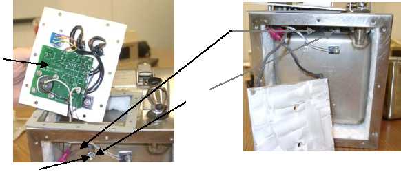
(2) Check the wires (1) between the thermistors (2) and the circuit board (3) to ensure the wires are not
broken, and are correctly connected and securely attached. Polarity is not important.
(3) Ensure the thermistors (2) are firmly attached to the HWR.
(4) Ensure that the thermistor mounted to the base of the main container (near the heater) is connected to
the circuit board location marked "BASE", and the thermistor mounted to the side of the main container is
wired to the circuit board location marked "SIDE". The "BASE" thermistor should have blue heat shrink
tubing around the wires to help identification. Unscrew and swap the thermistors if required.
t. Testing the Thermistors.
(1) With the thermistor (2) between 68 F and 77 F, measure the resistance between the two wires. The
resistance should be between 10,000 and 12,500 ohms. When the thermistor (2) is warmer, the
resistance is less and vice versa.
(2) If the thermistor resistance is out of tolerance, replace the thermistor as described in the next paragraph.
1
2
3
4