TM 10-7310-241-12&P
4-22.16 Change 1
4-16.1 REPLACING THE CONTROL PANEL ASSEMBLY FOR MODEL 471012 (Continued)
w. Repairing the Thermistors.
(1) If necessary, re-solder the wires (1) securely to their correct locations and touch up connections,
on both sides of the circuit board with conformal coating.
(2) If a repair was made, verify that the HWR is now operating correctly.
(3) If a defective thermistor (2) is still suspected, unsolder (and disconnect) the thermistor wires (1)
from the circuit board (3).
x. Inspecting the Thermal Switch.
NOTE
Perform the test at room temperature only.
NOTE
The thermal switch is a temperature-activated switch that breaks
contact (opens) when the temperature of the wall it is attached to
exceeds 239 OF and makes contact (closes) when the temperature
of that wall drops below 230 OF.
(1) Remove the control panel (Subparagraph 4-16.1a, steps (1) thru (4)).
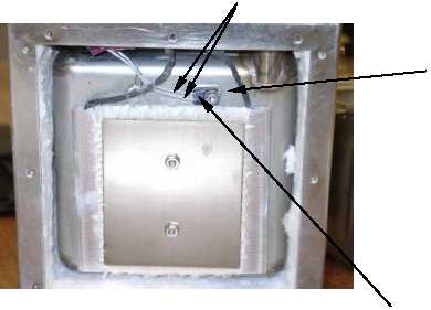
(2) Verify that the two thermal switch leads (1) are correctly connected to the circuit board and securely
attached. In some units the thermal switch may be connected directly between Pin A of the receptacle
and the POS terminal on the circuit board. In this latter case, a jumper will be installed between the
two terminals marked TS.
(3) Remove the base plate (Subparagraph 4-16.1q steps (1) thru (3)). Ensure the thermal switch (2) is
securely mounted to the base of the main container (3) adjacent to the heater.
1
2
3


