TM 5-3895-377-13&P
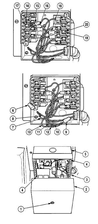
(6) Install wire (19) on terminal L1 (20) and tighten screw
(18).
(7) Install wire (15 and 16) on terminal 8 (17) and tighten
screw (14).
(8) Connect wires (10, 11, 12, and 13) and install wire nut
(9).
(9) Connect wires (7 and 8) and install wire nut (6).
(10)
Install burner controller (3) with two captive
screws (4) on controller subbase (5).
(11)
Install cover (2) with captive screw (1) on
controller (3).
NOTE
Follow-on Maintenance:
•
Install burner cover (page 4-296).
•
Remove wheel chocks (page 2-35).
END OF TASK
4-263

