
TM 5-4520-240-14
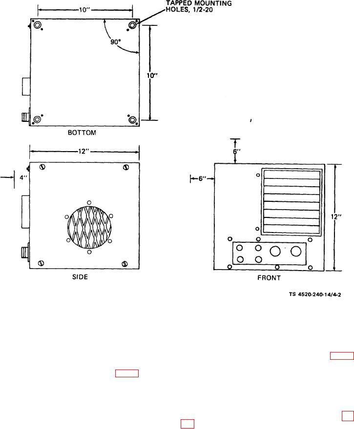
Figure 4-2. Base plan.
ing materials. Provide adequate fire-
(4) The side cover panel and the top cover panel are
interchangeable to provide alternate air intake in-
proofing insulation between the ex-
haust pipe and wall to prevent fire.
stallation.
(3) Connect a 1-inch exhaust pipe from the ex-
b. Installation.
haust connection on the heater to the outside (fig. 4-1),
(1) Secure heater to base or floor using -20 bolts
Seal all exhaust pipe joints using anti-seize compound
of suitable length (bolts not furnished with equipment).
(2) Connect the fuel inlet connector (fig. 1-2) on the
meeting specification JAN-A-669.
(4) When the heater is operated in a tightly con-
heater to the fuel source, using suitable lines and fit-
structed compartment which restricts inlet of combus-
tings. Make sure that the fuel supply is clean and free
tion air, it is recommended that combustion air be con-
of moisture. Check that connections do not leak.
nected to the combustion air inlet from an external
WARNING
source, using a hose or pipe. Invert the rain shield (fig.
Do not operate the heater in an
1-2) to provide a straight-through opening of the com-
enclosed space unless the exhaust
bustion air inlet. Combustion air piping is necessary to
gases are piped to the outside. Inhala-
prevent depletion of oxygen in an extremely tight
tion of exhaust fumes will result in
enclosure.
serious illness or death.
(5) Mount the room thermostat in an upright posi-
CAUTION
tion on an inside or insulated wall in the area to be
During operation, the exhaust pipe
heated. Do not install the thermostat in line with the
becomes hot enough to cause combus-
heater air inlet or discharge air flow, in a drafty posi-
tion of wood or other flammable build-
4-2