
TM 5-4520-240-14
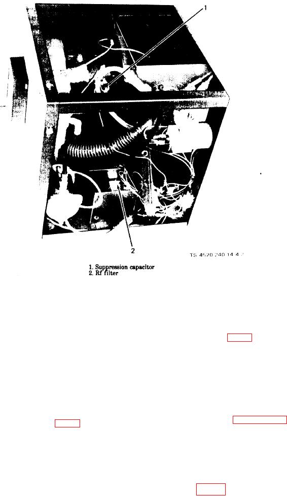
Figure 4-3. Primary radio interference suppression components.
4-15. Secondary Interference Suppression
b. An rf filter (2) is installed in the ignition power
Components.
supply. This device passes direct current but filters out
a. Component Identification. The secondary suppres-
the rf component of the input power.
sion components on the space heater are the shielded
4-14. Replacement of Suppression Compo-
high tension ignition cable (4, fig. 4-7) from the ignition
nents.
power supply (12) to the igniter (5), and the shielded ig-
niter.
WARNING
The ignition system of this space
b. Component Replacement.
heater contains dangerous voltages
(1) The ignition cable is manufactured as part of
which can cause severe electrical
the ignition power supply and is not serviceable sepa-
shock. Be sure to disconnect the power
rately. Refer to direct support maintenance to replace
plug before repairing the heater.
the ignition power supply if the ignition cable is defec-
tive.
Suppression Capacitor. Refer replacement of
(2) Replace the igniter per paragraph 4-30.
blower motor suppression capacitor (1, fig. 4-3) to direct
4-16. Testing of Radio Interference Sup-
support maintenance.
pression Components.
b. Rf Filter. Refer replacement of ignition power
Refer testing of suppression capacitor to direct support
supply rf filter (2) to direct support maintenance.
maintenance.
Section VIl. MAINTENANCE OF HEATER HOUSING ASSEMBLY
4-17. Description.
The warm air louver (fig. l-l) snaps into place, and you
a. Cover Panels and Case. The heater housing as-
can rotate it to any one of four positions to direct the
sembly contains and mounts the heater components.
flow of heated air up, down, or to either side. The top
4-7