TM 5-4520-240-14
defective.
(3) Check continuity of ON-OFF Switch (4) using a
multimeter set on OHMS scale. If switch is defective,
(3) Inspect the THERMO and POWER receptacles
tag and unsolder the two red and two violet leads from
in the control panel for cracks, damaged terminals, and
switch. Unscrew boot (3) and remove ON-OFF Switch.
signs of overheating. Report defective receptacles to
(4) Push in the cap on the fuseholder (5) and rotate
direct support maintenance.
the cap counterclockwise to remove it from the
c. Installation.
fuseholder. Remove the fuse (6) from the fuseholder.
(1) Installation of the control panel components is
Tag and unsolder the two red wires from the
the reverse of removal. Refer to figure 4-5.
fuseholder. Remove the fuseholder nut and pull the
(2) Use only rosin-core solder for soldered connec-
fuseholder from the front of the control panel. Remove
tions. Consult the wiring diagram (fig. 1-4) for correct
the spare fuseholder the same way.
wiring connections.
b. Cleaning and Inspection
(3) Secure the assembled control panel to the
(1) Clean the switch and fuseholders with a clean,
heater case with the five screws (1, fig. 4-5) and lock
dry cloth or a soft-bristle brush.
washers (2). Reinstall the top and side cover panels,
(2) Do not repair the ON-OFF switch or
connect the power plug, and check heater operation.
fuseholders. Replace these parts if they are damaged or
Section Vlll. MAINTENANCE OF FUEL SYSTEM
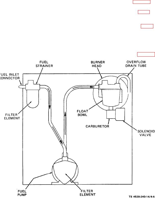
4-20. Description.
fuel pump, carburetor, solenoid valve, and the intercon-
netting lines and fittings. Refer to figure 4-6.
The space heater fuel system consists of a fuel strainer,
Figure 4-6. Fuel flow diagram.
4-11

