TM 5-4520-240-14
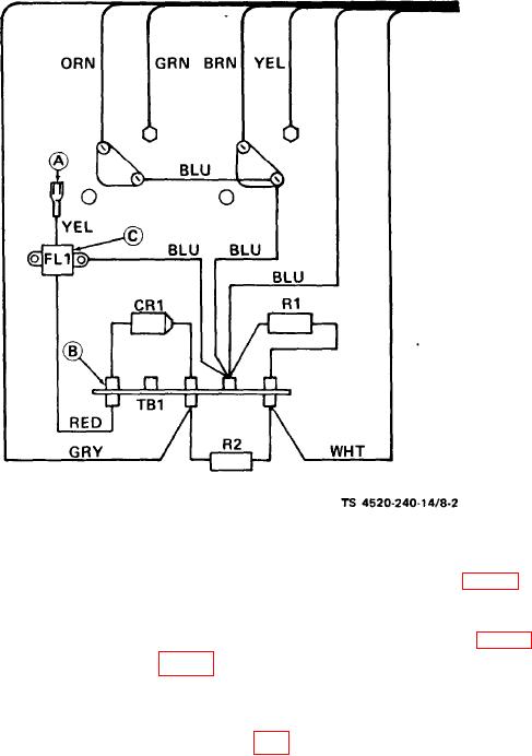
Figure 8-2. Ignition power supply wiring diagram.
substitute transistors (15, fig. 8-1) one at a time, and
NOTE
Resistors R1 and R2 and diode CR1 must be discon-
check for proper electrical output. Replace the defec-
nected from the circuit for the following tests. Alter-
tive transistor.
nate circuit paths within the power supply will con-
(7) Secure the cover (6, fig. 8-1) to the ignition
fuse the test results.
power supply with four screws (4) and lock washers (5).
(2) Check the resistance of resistor RI (10, fig.8-l).
Recheck per step b above.
Its resistance must be 47 ohms 10 percent. Replace if
defective.
8-4. Installation.
(3) Check the resistance of resistor R2 (11). Its
a. Position two external tooth lock washers (3, fig.
resistance must be 510 ohms 5 percent. Replace if
8-1) on the studs in the bottom of the heater housing.
defective.
Position the ignition power supply on the housing so
(4) Check resistance in both directions of diode
that the rear of the power supply engages the bracket
CR1 (12). In flow direction, resistance must be approx-
on the floor of the housing. Secure by installing the
imately 24 ohms. Infinite resistance must be indicated
nuts (1) and lock washers (2).
in the reverse direction. Replace a faulty diode.
b. Connect the high voltage ignition cable to the ig-
(5) If the above tests fail to indicate any defects,
niter on the burner head.
check transformer resistance between the tip of the ig-
c. Connect the yellow lead to the tab on the terminal
nition cable and ground. Resistance must be 700 ohms
board to which the other yellow leads are connected.
10 percent.
d. Install the top and side covers and insert the
(6) If resistance through the secondary of the igni-
power plug into the POWER receptacle. Attempt to
tion transformer is incorrect, replace the transformer.
start the heater and check for proper operation.
If transformer resistance is within the required range,
8-4

