
TM 5-4520-240-14
CHAPTER 9
REPAIR OF BURNER HEAD AND HEAT EXCHANGER
9-1. Description.
a. Burner Head. The burner head mounts on the end
of the heat exchanger, and provides mounting for the
igniter, glow plug, and carburetor. Combustion air sup-
plied by the combustion air blower enters the burner
head and passes into the burner head combustion
chamber, where it mixes with the fuel from the car-
buretor. This mixture is ignited and burns within the
burner head.
b. Heat Exchanger. The heat exchanger is a stainless
steel cylinder with a large surface area. It is open to the
burner head at one end, and contains an outlet for ex-
haust gases near the other end. The burning fuel and
air mixture heats the walls of the heat exchanger. The
ventilation air blower blows circulating air around the
outside of the heat exchanger, where the air picks up
heat from the heat exchanger before it passes through
the warm air louver into the enclosure to be heated.
9-2. Removal and Disassembly.
WARNING
T h e ignition system of this space
heater contains dangerous voltages
w h i c h can cause severe electrical
shock. Be sure to disconnect the power
plug before repairing the heater.
a. Disconnect the power and thermostat plugs. Dis-
connect the fuel supply and the exhaust piping.
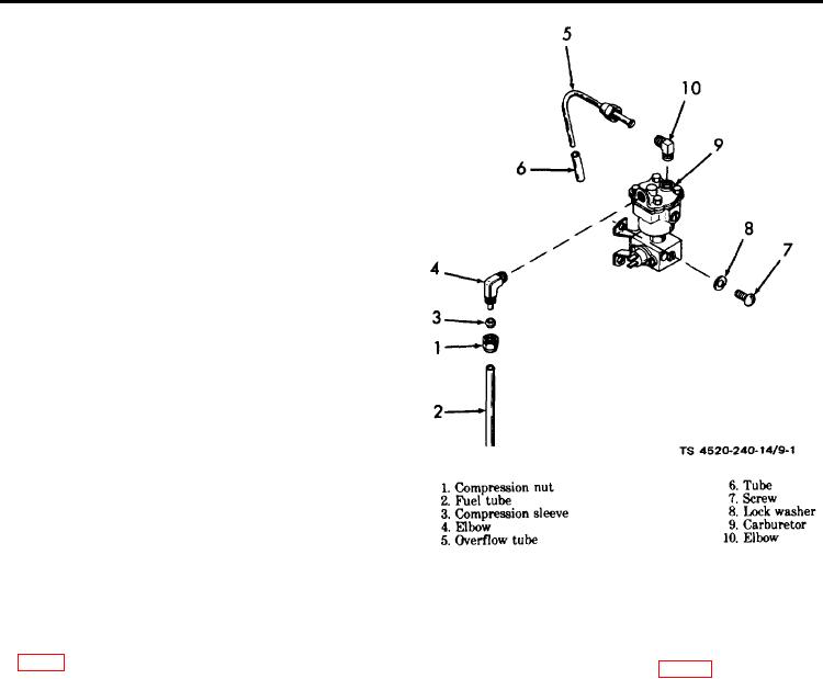
Figure 9-1. Carburetor installation exploded view.
Remove the top and side cover panels and warm air
c. Remove the four screws (7) and lock washers (8)
louver.
b. Disconnect the fuel preheat thermostat leads and
securing the carburetor to the burner head and remove
the fuel solenoid leads. Disconnect the compression nut
the carburetor.
(1, fig. 9-1) of fuel tube (2) at the elbow (4) in the car-
d. Loosen the hose clamps (1, fig. 9-2) and remove the
buretor inlet, Disconnect the overflow tube (5) from the
combustion air hose (2) from the blower outlet and the
elbow (10) on the top of the carburetor (9). Remove the
burner head inlet.
overflow tube and tube (6).
9-1