
TM 5-4520-240-14
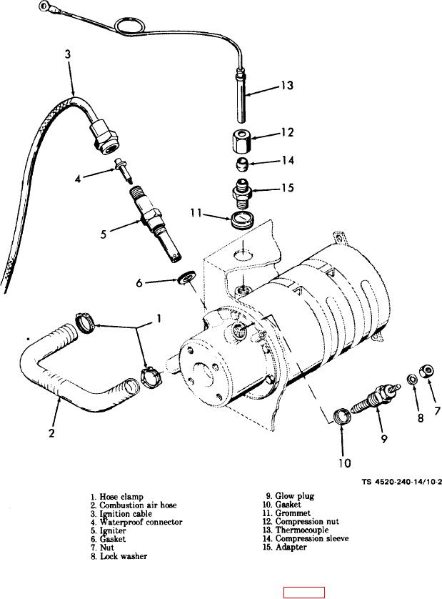
Figure 10-2. Burner head components, exploded view.
h. Use an Allen screw screwdriver to remove the
e. Unscrew the nut on the ignition cable (3) and
screws (1, fig. 10-3) and lock washers (2) securing the
remove the cable and waterproof connector (4).
burner head (3) to the heat exchanger housing (24).
Unscrew the igniter (5) and remove the igniter and
Remove the burner head and gasket (4).
gasket (6) from the burner head.
i. Remove the overheat thermostat. Remove the nut
f. Remove the nut (7) and lock washer (8) and discon-
(5), lock washers (6 and 8), and screw (7) securing the
nect the blue lead from glow plug (9). Unscrew and
bracket (9) to the heat exchanger (22); remove the
remove the glow plug and the gasket (10) from the
bracket.
burner head.
j. Remove the four screws (10) and lock washers (11)
g. Disengage the grommet from the hole in the heat
securing the exhaust connection (12) to the heater case.
exchanger housing. Unscrew the compression nut (12)
Remove the exhaust connection, gasket (13), and ex-
on the thermocouple (13) and remove the assembled
haust washer (14).
compression sleeve (14), compression nut, and ther-
mocouple from the heat exchanger.
10-2