
TM 5-4520-241-14
1.
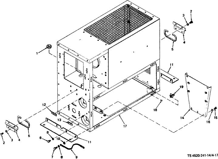
Grommet
10.
Lock washer
2.
Screw
11.
Mounting bracket
3.
Lock washer
12.
Label, fuel receptacle
4.
Handle plate
13.
Label, power receptacle
5.
Handle
14.
Bulkhead
6.
Screw
15.
Screw
7.
Screw
16.
Lock washer
8.
Lock washer
17.
Heater case
9.
Grounding strap
18.
Rivet
19.
Turnlock fastener receptacle
Figure 4-17. Heater case assembly.
(2) Remove screws (2), lock washers (3), handle plates (4), and handles (5) from both the front and the rear of
the heater case.
(3) Remove screws (6 and 7), lock washers (8 and 10), and grounding strap (9). Remove mounting brackets (11)
from the heater case.
(4) Remove labels (12 and 13) only if they are illegible.
4-50