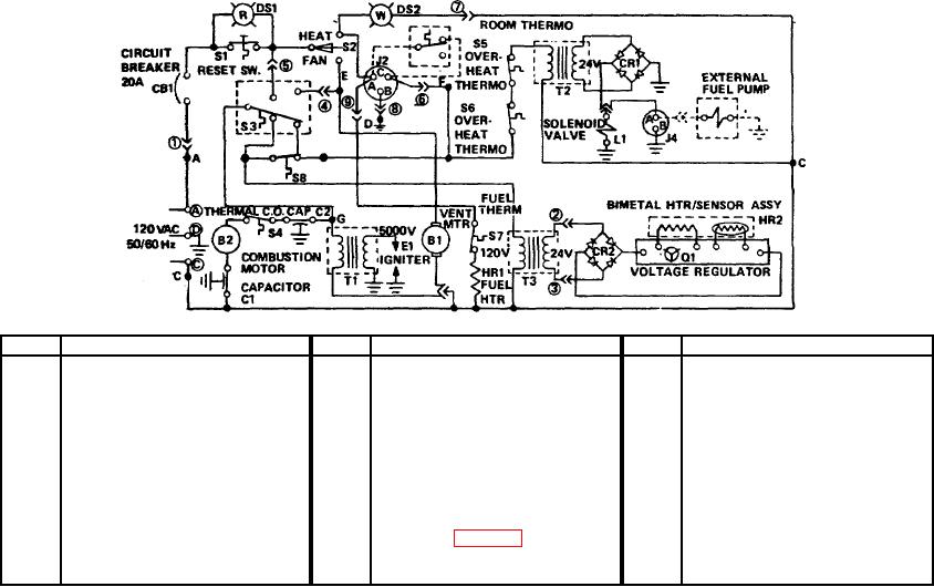
TM 5-4520-241-14
KEY
ITEM
KEY
ITEM
KEY
ITEM
B1
Ventilating motor
E1
S2
Toggle switch (HEATER-OFF-
B2
Combustion motor
HR1
Fuel heater
FAN)
C1
Capacitor, interference
HR2
Bimetal heater/sensor
S3
Flame switch
suppression
(Time delay)
S4
Thermal cutout switch
C2
Capacitor, interference
J2
ROOM THERMO receptacle
S5
Overheat thermostat switch
suppression
J4
EXTERNAL FUEL PUMP
S6
Overheat thermostat switch
CB1
Circuit breaker, 20 amps
RECEPTACLE
S7
Fuel thermostat switch
CR1
Rectifier (Fuel pump power
L1
Solenoid valve
S8
Safety switch
supply)
P1
Male plug (Control box)
T1
Ignition transformer
CR2
Rectifier (Time delay)
(see 2, fig. 4-15)
T2
Fuel pump power supply
DS1
Incandescent lamp (Red)
Q1
Transistor
DS2
Incandescent lamp (White)
S1
Switch, SPST (RESET)
T3
Time delay transformer
TS4520-241-14/4-25
Figure 4-25. Electrical system operation.
(3) When ignition occurs, and the flame switch senses the proper temperature in the heat exchanger, the flame
switch will trip to its running position (closing the normally open contacts). This action deenergizes HR2 and the time
delay assembly, and energizes ventilating motor B1 which forces air from the enclosure past the heat exchanger. Note
that the 120 volt input to the flame switch is ahead of switch S2, and so permits heater purge further described in
paragraph d.
(4) Safety switch S8 is a safety thermostat which duplicates the item delay circuit functioning of the flame switch.
S8 always opens before the flame switch transfers on heat rise, and always closes more slowly on heat shut down. If for
any reason the flame switch should fail to close following a combustion failure, this switch will reclose and energize the
time delay shutdown circuit to protect the heater from damage.
4-67

