
TM 5-4520-241-14
1.
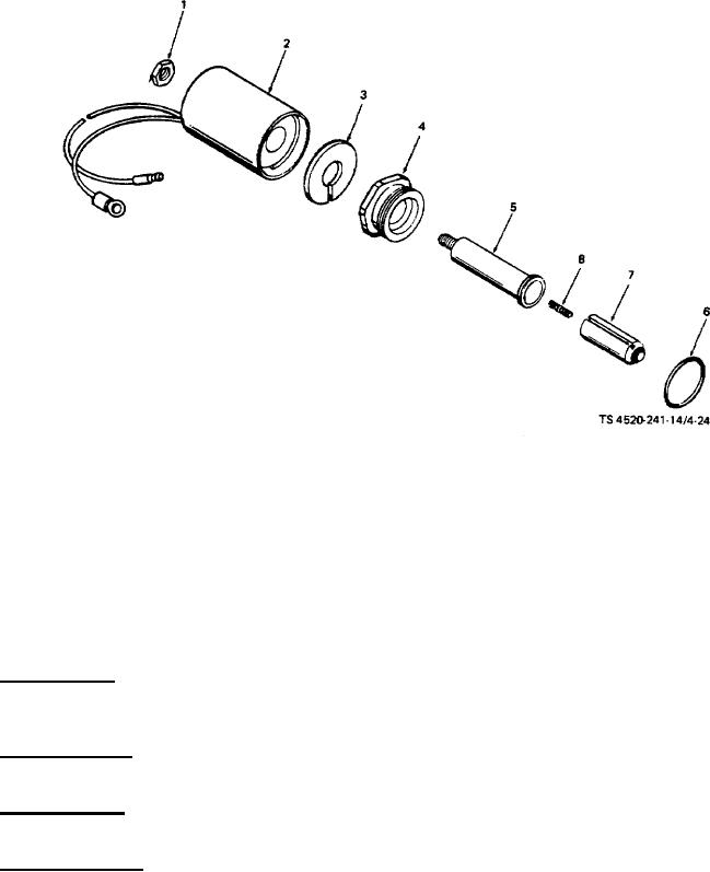
Nut
5.
Stem
2.
Coil
6.
Preformed packing
3.
Washer
7.
Plunger
4.
Nut
8.
Spring
Figure 4-24. Solenoid assembly.
SECTION X. MAINTENANCE OF ELECTRICAL SYSTEM
4-34.
DESCRIPTION.
a. Wiring Harness. The wiring harness simplifies electrical connections inside the heater case. The female
receptacle accepts the male plug from the control box wiring harness. Leads go to the power and external fuel pump
receptacles at one end, and to the terminal board and other electrical components at the other end.
b. Combustion Motor. The combustion motor furnishes a stead supply of fresh air through the air duct directly to the
burner head.
c. Ventilating Motor.
The ventilating motor forces fresh, cool air across the heat exchanger to provide warm
ventilating air.
d. Safety Thermostats. There are four safety thermostats. One is on the combustion motor to prevent it from
overheating, and three are in the heat exchanger compartment. The flame switch can also be regarded as a safety
thermostat since it will not permit normal heater operation until proper ignition occurs.
4-65