
TM 5-4520-241-14
4-38.
FUEL PUMP POWER SUPPLY.
a. Removal.
WARNING
This space heater contains dangerous voltages which can cause severe electrical
shock. Be sure to disconnect the power plug before repairing the heater.
(1) Disconnect the power plug from the power receptacle.
(2) Open the side access door.
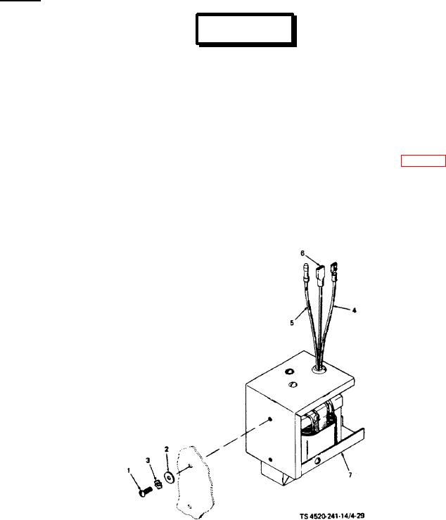
(3) Remove the entire fuel pump power supply assembly by removing two screws (1, fig. 4-29), washers (2), and
lock washers (3).
(4) Disconnect the fuel pump power supply electrical leads by pulling the white lead (4) off the terminal strip and
the yellow lead (5) out of the connector. The gray lead (6) is connected to the lower overheat thermostat, which must be
removed from the bulkhead before pulling off the terminal.
1. Screw
4.
White lead
2. Washer
5.
Yellow lead
3. Lock washer
6.
Gray lead
7.
Fuel pump power supply
Figure 4-29. Fuel pump power supply.
4-75