TM 5-4520-253-13
REPAIR PC BOARD ASSEMBLY WIRING RECEPTACLE (CONT)
5.
6.
7.
8.
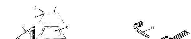
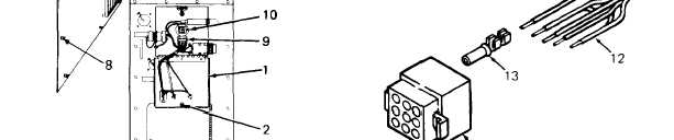
Pull receptacle (10) out of side of heater case. Cut off and discard cable ties (11 ) as needed to
allow access to harness wires (12).
Tag wires (12) and cut as close to receptacle (10) as possible. Discard receptacle.
Strip 1/4 inch (6.35 mm) of insulation from end of each wire (12). Crimp male terminal
on each wire.
Refer to table 4-2 and push wire terminals (13) into numbered sockets in receptacle (10).
colors and socket numbers must be in accordance with the table.
Table 4-2. Receptacle Wiring Sequence
(13)
Wire
Wire Color
I
Socket No.
Black
Brown
Red
White
Yellow
Orange
Grey
Green
Not used
1
2
3
4
5
6
7
8
9
4-22