TM 9-2540-207-14&P
These maintenance instructions provide a step by step approach to access the necessary components and perform
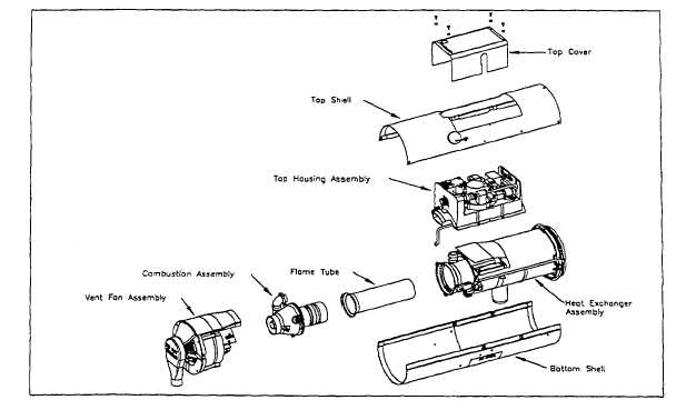
maintenance. Throughout these instructions there will be references to figures that will assist in locating the various
assemblies and parts.
To aid in repairs, the Heater can be broken into five major assemblies:
1.
shell assembly
2.
vent fan assembly
3.
combustion assembly
4.
heat exchanger assembly
5.
top housing assembly
Figure 5-1. Heater, Major Assemblies
Test Stand Installation & Removal
TM 9-4910-755-13&P for information regarding installation and removal of the Heater on a Test Stand.
Note: For service, the Heater may be set on the vent air discharge end. This
permits good access to the shells and most subsystems.
DO NOT set the Heater with the Diagnostic Display Label facing downwards. If this
configuration is necessary for removal of the Vent Sensor or Heat Exchanger,
ensure that any residual fuel in the Burner or Heat Exchanger is first drained.
!CAUTION!
DO NOT set the Heater on the vent air INLET end (i.e., On the casting marked “DO
NOT REMOVE") as the Heater will be unstable and may tip over;
5-2